Wired Xbox 360 LED Lighted Controller Mod
Start with an Original Microsoft wired or wireless Xbox 360 controller. Use the following tutorial to get to the circuit board This is a multi part mod, first changing the color of the LED's on the circuit board then adding 4 always on LED's to the 360 dome followed by lighting the start and back buttons, ABXY button lighting, and the rumble motor configuration.
Tools-
Variable temp soldering station or 15watt iron
Hot Glue Gun
Phillips #1
wire stripper
X-acto knife with #11 blade and old style aluminum handle
Drill with 17/64 bit
Plyers
Supplies-
.22 60/40 rosin core solder
Surface Mount Led
Hot Glue
30 Gauge Wire
Resistor
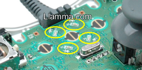
Replacing the Surface Mount LED's With the circuit board exposed we can get down to the detail. You will need to remove four LED's they can be found around the upper center of the PCB. So yeah they are pretty dang small. If you have never wielded a soldering iron stop right now and put everything back how it was! If you are a fearless soldering god continue on...
|
|
To get our first one done it required two of us. We setup with one of us on the tweezers and each with an iron. Irons set to 550 F we went to work, get a good grip on the LED and a quick touch to the solder from each side simultaneously did the trick. We then busted out the hot tweezers we have never had occasion to use before and found that a much easier option. |
| But if you are doing this alone we found the slickest way is to bathe the LED in solder and use the iron to wipe it away and then just deposit it on your sponge. Its important to clean up after, you do not want much solder on the pads during reinstallation. And of course, be careful not get any on the sensitive gray black pads in the area. | |
|
|
Re-installing is much easier and a one man job, like any other tiny SMT component line it up, tack one side and then the other. They do sort of have a tendency to float up and if there is too much solder left so don't be afraid to offer a little gentle down force while heating the solder. Note the polarity marks for the led and make sure to put them on the right direction. |
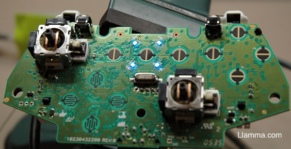
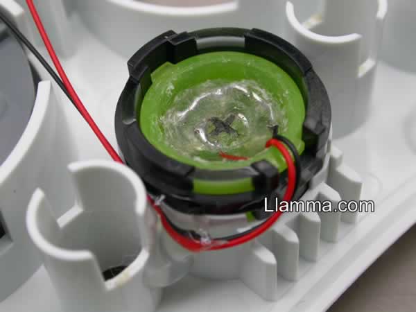
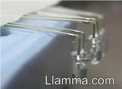
Lighting the Dome- To get the dome illuminated we tried several variations, one LED, two LED's, but ended up going with four for full bling. With blue LED's, 4 in parallel a 22 Ohm resistor is connected to all positive legs and the resistor is connected to the positive source. All negative legs (short ones) are connected to ground. When using 4 red LED's a 47 Ohm resistor was used.
 |
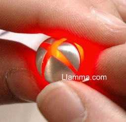
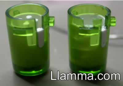
There are more than a couple ways you can get all the positive contacting each other and also get all the negative leads contacting each other. In this photo you see an untouched 360 button as well as a completed blue LED mod. In the following photos we will be demonstrating a dual ring style wiring pattern that is easier to accomplish. |
 |
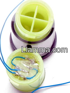
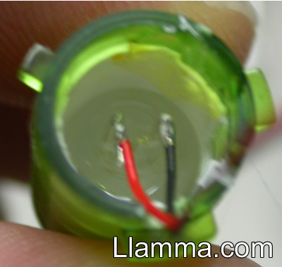
Start by making some room for the led leg wiring by snipping out some of the support of the button. Make sure to leave a bit in the middle for strength and to give you a reference of how far you can fill at the end. I like to leave a plus sign in the middle for a handy way to remember which way the led's should be wired. |
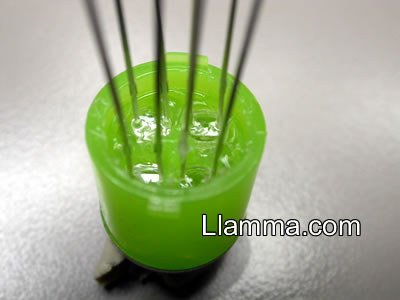 |
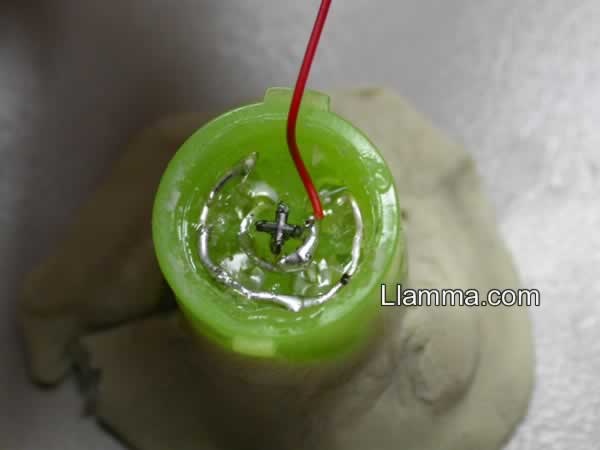
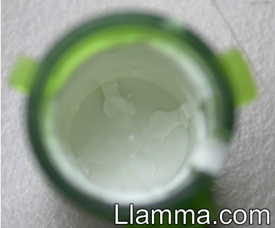
Stick the tip of the glue gun in a hole and squirt some hot glue in to about 3/4 full. The idea is to fill the hole but not so far that you don't have room to work and keep the level low enough so the button still works properly. Insert the led with the LONG leg toward the center plus sign.. get it positive :) You want to push the led in far enough so you have room to work but not all the way to the front so the light spreads well. |
 |
You should end up with something like this. Note the plus in the center and the long legs all set closest to it. |
 |
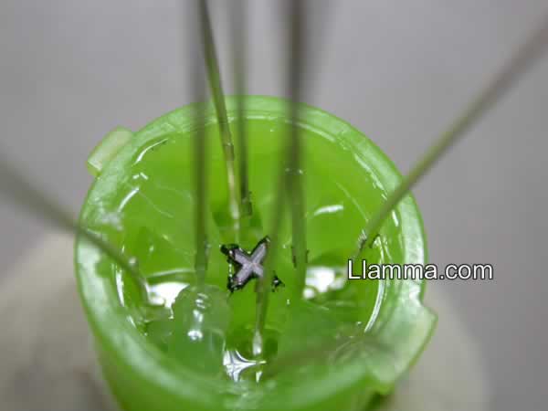
Now you want to start folding and trimming the legs in a way that forms a ring with the legs touching one another. The key is to make the ring of legs lower than your center plus sign so your level will not be to high. Look at the photo and note where you want to start and finish the outside ring. You want to leave a gap between the larger of the keyed tabs of the button. The wire will eventually run out of that gap in the control case. |
 |
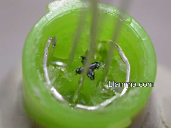
When your completed you should have something like this. Again, note the gap on the outer ring coincides with the larger keyed tab. Mmm rings, 360... rings... coincidence? Now go through and solder all of the joints of the ring and create a connection between all of the led's. Remember there is a inner ring and a outer ring that should not be connected to each other. |
 |
Next solder a wire about 6" long to the inside ring. This will be your positive lead, remember the plus sign you left :) Again you want to place the wire so that it will be running over the larger of the keyed tabs. |
 |
Now attach a 6" long wire to the outside ring which is negative. |
 |
Position your wires so they are running out over the larger of the keyed tabs. |
 |
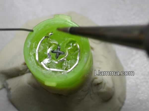
If you have done it right you should have some open space where you were wiring and the center plus should be the highest area inside the button. This is a great time to hook the led's up with the proper resistor for the parallel led's you have just wired and make sure the whole thing works. After you have verified that everything is working ok you can fill any extra space with hot glue. MOST IMPORTANT, you must not fill the button past the center plus signs level. If you do the button will always be pressed and will not work properly. I just happen to have the perfect tool for making a nice clean level surface on the inside of the button.. it is a large X-acto knife's butt end. I'm sure you can find something that will work. |
 |
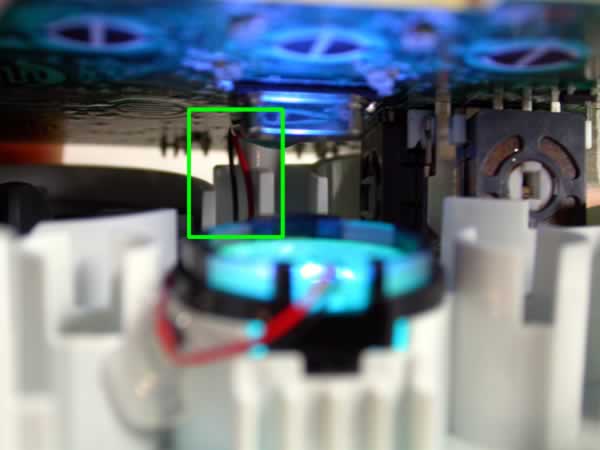
Now place your status ring and the guide button back into the controller with the wires exiting the button area through the large gap in the status ring. Leave a very small amount of slack for button movement and tack the wires into the crack like so. |
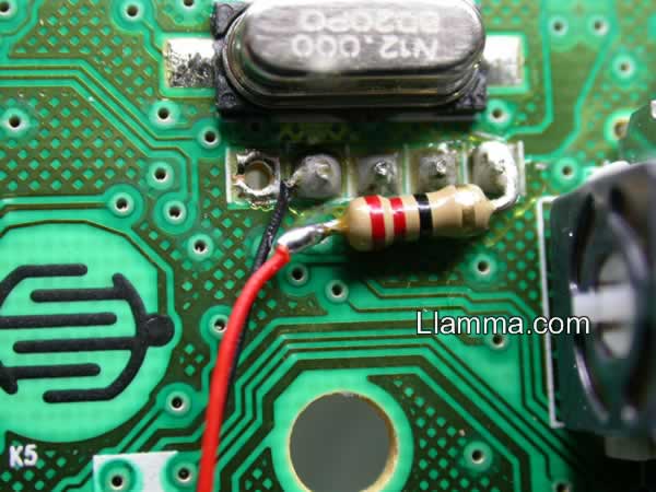 |
Next grab your controller PCB and flip it over and look where the USB cable connects to the board. Note which contact is red and which is black. Connect to the red positive lead the proper resistor for the amount and configuration led's (this was four blue led's so we used a 22ohm resistor). Now connect your positive wire from the guide button to the other end of the resistor. Next connect your negative wire from the guide button to the black negative lead of the controller. |
| A little dab of hot glue will keep the whole works in check and make sure nothing can short. You can now plug the controller into the USB port and it should be gravy. | |
 |
Reinstall all of your buttons, rubber contact pads, thumb stick, d-pad and front and back pieces. Then place the controller PCB board onto the top case. When closing this part of the controller take note of the photo and make sure your wires are free and clear of the screw hole and standoff area so you don't end up with shorts or cut wires. Get it all back in place, replace your rumble motors, slap your back cover on and your in like flint baby.. your all done! |
| The button starts out like this | |
| We start by wrapping a button in some foam of protection and then grasp in a normal pliers | |
| Drilling out the button- we found that a smaller drill bit than the perfect fit size worked best, it gives the bit a chance to bounce around and dice up the four pegs. | |
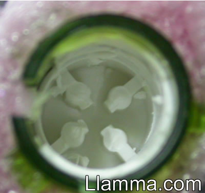 |
empty the chopped-up bits of button frequently, keep checking the depth getting there... |
 |
oh so close... but gotta go a bit further those bits of plastic will leave a shadow |
 |
there nice and smooth no bumps to leave shadows. |
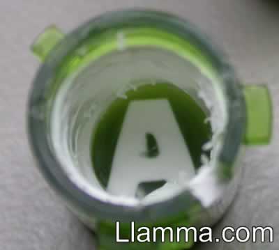 |
If we go a little deeper we dip into the transparent outer leaving the letter floating. This can be an interesting effect but ends up looking a little hot spotted with a white LED. If you want to go with this method I would recommend using an LED of the corresponding colors rather than white. |
 |
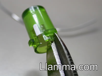
We found cutting a portion of the button above the largest plastic tab was the best option for routing the 30AWG wire. There is already plenty of space in the controller face to route through. If you were to use the existing notch all the buttons have to route the wire that would work fine for making the button but that lines up with a part of the face that would have to be cut. |
 |
A little snip with some shears and a little clean up of the rough edges with an xacto and we are in business. |
 |
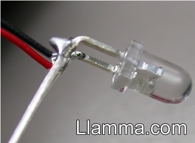
Preparing the LED, We then bend the LED legs close to the LED at a 90 degree angle. |
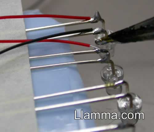 |
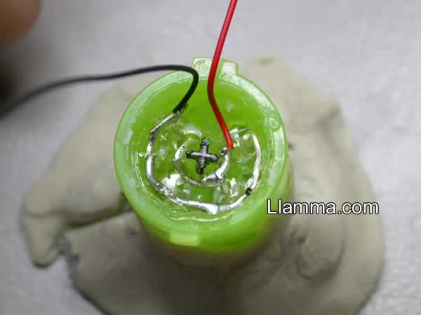
Start with two colors of 30AWG wire, a dark one for ground and a bright one for hot, we will be using black and red for this example. |
 |
once the wires are soldered bend them away from the legs |
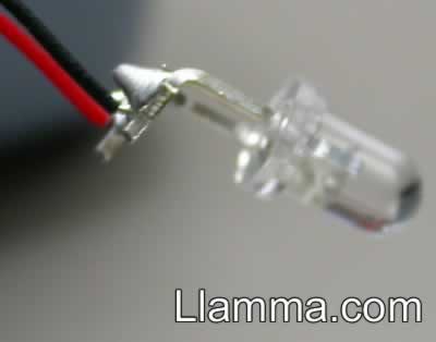 |
with a quick snip we have an LED on a string. |
 |
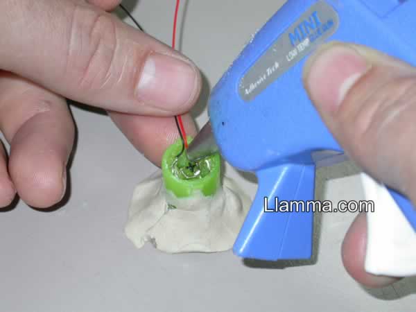
we fill our button about half way with hot glue and submerge our LED |
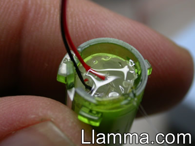 |
then top it off with some more glue |
 |
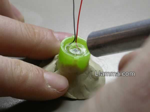
Jamb the x-acto handle into the button to squish out any excess hot glue. The glue exposed to the handle will solidify quickly. To remove the handle twist the button off, this causes the hotglue to release without warping which may occur if pulled straight out. |
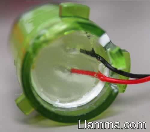 |
This should make a nice flat layer at the same height as the original button. It is important to get a level surface at the original height to allow for normal operation of the buttons. If it is even the smallest bit higher than it should be the button will not have the tactile response of the rubber flexing-pop as it will already be partially flexed. |
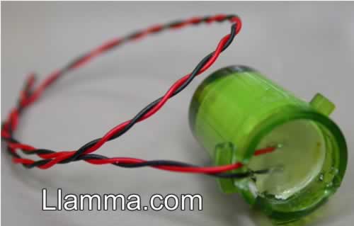 |
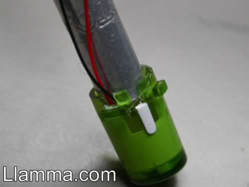
Twist the wires together to make it more manageable when it comes to installation. Repeat the process for all the other buttons. If you make a mistake you can always drill out the button again, so it may be a good idea to get a couple extra LED's for good measure. |